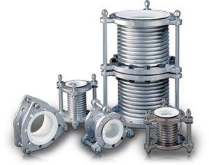
PTFE Lined Metal Expansion Joints
ChemTite® Ethylene™ FlexArmor® Flexijoint PTFE lined expansion bellows combine the high-pressure rating of a metallic expansion joint with the high temperature and near-universal corrosion resistance of PTFE. They are designed for services where the unreinforced Flexijoint PTFE bellows is unsuitable.

Product Features & Benefits
- SEAMLESS, HEAVY WALLED, ISOSTATICALLY MOLDED PTFE LINERS: provide excellent resistance to permeation. This high integrity liner offers a superior alternative to the conventional PTFE spray coated or seamed liner. They are subjected to uncompromising quality control before and after lining of the bellows.
- HIGH PRESSURE RATINGS: for FlexArmor® bellows are as high as 285 psig.
- UNIFORM WALL THICKNESS AND INCREASED FLEXIBILITY: the metallic outer bellows features uniform wall thickness and multiple ply construction for increased flexibility.
- AVAILABLE OPTIONS: bellows are available in most nickel alloys including Monel, Inconel and various types of stainless steels. Available designs include universal joints, hinged-pinned, slotted, and gimbal types.
- VERSATILE MANUFACTURING TECHNIQUES: accommodate customization of FlexArmor® bellows' flanging, overall length, movements, and spring rates.
- CUSTOM ENGINEERED FOR SPECIFIC PROCESS REQUIREMENTS: FlexArmor® can be custom engineered for specific process requirements while maintaining high flex cycle fatigue life.
FlexArmor® Standard Construction
- FLANGING: Class 150 carbon steel flanges with clearance holes per ANSI5.
- BELLOWS CARCASS: Fabricated from type 321 stainless steel.
- LINER: Heavy walled, isostatically molded, seamless PTFE.
- TIE RODS: FlexArmor® bellows are supplied with three(3) threaded, carbon steel tie-rods that have been set to the maximum design length to prevent over-extension of the bellows in service.
FlexArmor® Options
Tandem Expansion Joint/Bellows
Constructed from two FlexArmor® bellows, this unit is designed for applications where extra-long face to face dimensions are required to provide increased axial movement.
A custom, overall length can be specified.

Universal Expansion Joint/Bellows
Constructed from two FlexArmor® Flexijoint bellows connected with a PTFE lined pipe section, these units are designed for use where large lateral displacements are encountered or where minimal lateral reaction forces are desired. This is critical when mating to glass, glass lined steel and graphite nozzles. The overall length of the unit is tailored to meet lateral, axial and angular displacement, and load (i.e. spring rate) constraints.

Hinged Expansion Joint/Bellows
Hinged expansion bellows are useful when support of an adjacent pipe spool by the expansion bellow's flanges is required. These bellows allow angular movement of the adjacent piping while restricting axial and lateral displacement. A hinged, pinned and slotted expansion joint design is frequently used where large lateral or angular movements are expected.

Specifications
- WETTED SURFACES: PTFE
- MAX PRESSURE: 285 psi
- MAX TEMPERATURE: 400°F
- METAL BELLOWS: Type 321 Stainless Steel
- FLANGED MATERIAL: A105 or A516 GR70
- TIE RODS: C1040
- LOCK NUTS: Zinc Plated Carbon Steel
- FLANGED DRILLING: ANSI B16.5 XL150
Engineering Data

Nominal Diameter | Bellows Inside Diameter (in) | Metal Bellows Wall (in) | PTFE Liner Thickness (in) | Flare Face (in) | Flange Outside Diameter (in) | Flange Thickness (in) | Number of Holes | Hole Diameter (in) | Bolt Circle Diameter (in) | Maximum Allowable Working Pressure |
1-1/2 | 1 13/16 | 0.016 | 0.09 | 2 7/8 | 5 | 11/16 | 4 | 5/8 | 3 7/8 | 285 psi |
2 | 2 5/16 | 0.018 | 0.095 | 3 5/8 | 6 | 3/4 | 4 | 3/4 | 4 3/4 | |
3 | 3 5/16 | 0.024 | 0.1 | 5 | 7 1/2 | 15/16 | 4 | 3/4 | 6 | |
4 | 4 1/4 | 0.024 | 0.11 | 6 3/16 | 9 | 15/16 | 8 | 3/4 | 7 1/2 | 175 psi |
6 | 6 1/16 | 0.036 | 0.12 | 8 1/2 | 11 | 1 | 8 | 7/8 | 9 1/2 | |
8 | 8 | 0.042 | 0.131 | 10 5/8 | 13 1/2 | 1 1/8 | 8 | 7/8 | 11 3/4 | |
10 | 10 | 0.048 | 0.141 | 12 3/4 | 16 | 1 3/16 | 12 | 1 | 14 1/4 | |
12 | 11 15/16 | 0.06 | 0.152 | 15 | 19 | 1 1/4 | 12 | 1 | 17 | |
14 | 13 1/8 | 0.072 | 0.16 | 16 1/4 | 21 | 1 3/8 | 12 | 1 1/8 | 18 3/4 | |
16 | 15 | 0.072 | 0.175 | 18 1/2 | 23 1/2 | 1 7/16 | 16 | 1 1/8 | 21 1/4 | 150 psi |
18 | 16 7/8 | 0.072 | 0.191 | 21 | 25 | 1 9/16 | 16 | 1 1/4 | 22 3/4 | |
20 | 18 13/16 | 0.072 | 0.198 | 23 | 27 1/2 | 1 11/16 | 20 | 1 1/4 | 25 | |
24 | 22 5/8 | 0.072 | 0.222 | 27 1/4 | 32 | 1 7/8 | 20 | 1 3/8 | 29 1/2 | 125 psi |
FlexArmor® bellows can be designed to meet a broad range of applications. The tables found in this section are for neutral length and axial movements are for standard units.
The neutral, face-to-face length and the maximum allowable axial movements for FlexArmor® Flexijoints are given in Table 2 below. The numbers listed in Table 2 represent the normal overall length of bellows as shipped. The axial extension and compression are the maximum movements from the neutral position. A FlexArmor® bellows can be supplied to your exact neutral length and/or movement specifications. Please consult the factory with your unique requirements.
Neutral Length and Allowable Axial Movements (+Extension / -Compression)
Nominal Diameter | 4 | 5 | 6 | 7 | 8 | 9 | 10 | 11 | 12 | |||||||||
1-1/2 | Not Available | Not Available | 5 | +3/16 -5/16 |
5 1/2 | +7/32 -3/8 |
6 | +1/4 -7/16 |
6 1/2 | +9/32 -1/2 |
7 | +5/16 -9/16 |
7 1/2 | +11/32 -5/8 |
8 | +3/8 -11/16 |
||
2 | 5 | +3/16 -5/16 |
5 1/2 | +7/32 -3/8 |
6 | +1/4 -7/16 |
6 1/2 | +9/32 -1/2 |
7 | +5/16 -9/16 |
7 1/2 | +11/32 -5/8 |
8 | +3/8 -11/16 |
||||
3 | 5 7/8 | +1/4 -7/16 |
6 7/16 | +9/32 -17/32 |
7 | +5/16 -5/8 |
7 9/16 | +3/8 -22/32 |
8 1/8 | +7/16 -13/16 |
8 11/16 | +1/2 -29/32 |
9 1/4 | +9/16 -1 |
||||
4 | 6 3/8 | +9/32 -1/2 |
7 | +5/16 -19/32 |
7 5/8 | +11/32 -11/16 |
8 1/4 | +13/32 -25/32 |
8 7/8 | +15/32 -7/8 |
9 1/2 | +17/32 -31/32 |
10 1/8 | +19/32 -1 1/16 |
||||
6 | 7 1/4 | +11/32 -5/8 |
8 | +13/32 -3/4 |
8 3/4 | +15/32 -7/8 |
9 1/2 | +9/16 -1 |
10 1/4 | +5/8 -1 1/8 |
11 | +11/16 -1 1/4 |
11 3/4 | +3/4 -1 3/8 |
||||
8 | 6 1/2 | +1/4 -15/32 |
7 5/16 | +11/32 -5/8 |
8 1/8 | +7/16 -25/32 |
8 15/16 | +17/32 -15/16 |
9 3/4 | +5/8 -1 3/32 |
10 9/16 | +23/32 -1 1/4 |
11 3/8 | +13/16 -1 13/32 |
12 3/16 | +29/32 -1 9/16 |
13 | +1 -1 3/4 |
10 | 7 | +9/32 -1/2 |
7 7/8 | +3/8 -21/32 |
8 3/4 | +15/32 -13/16 |
9 5/8 | +9/16 -31/32 |
10 1/2 | +21/32 -1 1/8 |
11 3/8 | +3/4 -1 5/16 |
12 1/4 | +27/32 -1 1/2 |
13 1/8 | +15/16 -1 11/16 |
14 | +1 1/16 -1 7/8 |
12 | 7 3/4 | +5/16 -9/16 |
8 3/4 | +13/32 -3/4 |
9 3/4 | +1/2 -15/16 |
10 3/4 | +5/8 -1 1/8 |
11 3/4 | +3/4 -1 5/16 |
12 3/4 | +7/8 -1 1/2 |
13 3/4 | +1 -1 11/16 |
Note: Flexarmor bellows cannot be subjected to simultaneous full-rated axial, lateral and angular misalignments. Consult Ethylene Corporation for specific information. |
|||
14 | 8 3/4 | +5/16 -9/16 |
9 15/16 | +13/32 -3/4 |
11 1/8 | +1/2 -15/16 |
12 5/16 | +5/8 -1 1/8 |
13 1/2 | +3/4 -1 5/16 |
14 11/16 | +7/8 -1 1/2 |
15 7/8 | +1 -1 11/16 |
||||
16 | 9 1/4 | +3/8 -11/16 |
10 1/2 | +1/2 -15/16 |
11 3/4 | +5/8 -1 -3/16 |
13 | +25/32 -1 7/8 |
14 1/4 | +15/16 -1 11/16 |
15 1/2 | +1 3/32 -1 15/16 |
16 3/4 | +1 1/4 -2 3/16 |
||||
18 | 9 3/4 | +3/8 -11/16 |
11 | +1/2 -15/16 |
12 1/4 | +5/8 -1 3/16 |
13 1/2 | +25/32 -1 7/8 |
14 3/4 | +15/16 -1 11/16 |
16 | +1 3/32 -1 15/16 |
17 1/4 | +1 1/4 -2 3/16 |
||||
20 | 10 1/2 | +7/16 -3/4 |
11 7/8 | +9/16 -1 |
13 1/4 | +11/16 -1 1/4 |
14 5/8 | +27/32 -1 1/2 |
16 | +1 -1 3/4 |
17 3/8 | +1 5/32 -2 |
18 3/4 | +1 5/16 -2 1/4 |
||||
24 | 11 1/4 | +7/16 -3/4 |
12 11/16 | +9/16 -1 |
14 1/8 | +11/16 -1 1/4 |
15 9/16 | +27/32 -1 1/2 |
17 | +1 -1 3/4 |
18 7/16 | +1 5/32 -2 |
19 7/8 | +1 5/16 -2 1/4 |
Literature
Contact Us
Give us a call at 616-554-4600 or fill out this form and one of our experts will be in touch as soon as possible.
* marks required fields
Technical Support Inquiry Request a Quote